satlog.io Data Logger
Connectivity & Electrical
The Data Logger powers the modem when connected. In a standalone configuration, the Data Logger alone uses about 50-100mA, but the majority of the power is consumed by the modem. See details about the modem's electrical characteristics in Modem Electrical.
You can use any one option to power the Data Logger, do not connect multiple power sources.
USB
satlog will power on and function by using a USB C cable to either the USB port marked USB Power or USB Data.
CAN1 Connector (CAN, NMEA2000, Modbus, Power)
The CAN1 port is pin compatible with VE.Can but will itself not power the network. Victron devices like the MultiPlus will provide power that the satlog can use, see details here. Max voltage 36 volts, minimum 9 volts.
CAN1 pins used with the Data Logger, note numbering is left (8) to right (1) looking at the port.
| Pin # | Name | Description |
|---|---|---|
| 8 (Left) | CAN L | CAN1 bus low |
| 7 | CAN H | CAN1 bus high |
| 6 | +36V | Power supply, 9-36VDC |
| 5 | Modbus Data B+ | Positive data signal |
| 4 | Modbus Data A- | Negative data signal |
| 3 | GND | Power ground |
| 2 | X | Not in use |
| 1 (Right) | X | Not in use |
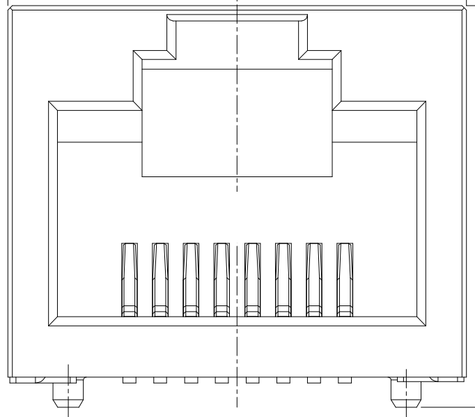
CAN2 Connector (CAN, NMEA2000, Modbus)
The CAN2 port is onlt available on v0.13 and later Data Loggers. The RJ45 port is pin compatible with VE.Can. The Modbus pins are the same as CAN1 Connector making for easy daisy chaining with other Modbus equipment.
CAN2 pins used with the Data Logger, note numbering is left (8) to right (1) looking at the port.
| Pin # | Name | Description |
|---|---|---|
| 8 (Left) | CAN L | CAN2 bus low |
| 7 | CAN H | CAN2 bus high |
| 6 | X | Not in use |
| 5 | Modbus Data B+ | Positive data signal |
| 4 | Modbus Data A- | Negative data signal |
| 3 | X | Not in use |
| 2 | X | Not in use |
| 1 (Right) | X | Not in use |
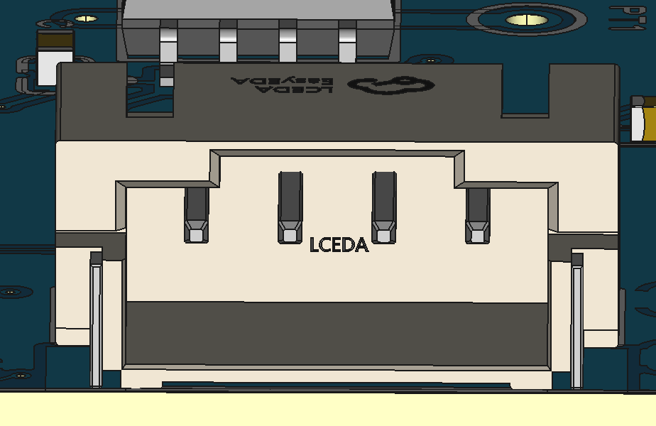
Serial Interface (VE.Direct)
The serial interface of the Data Logger is galvanically isolated and the IO level desired (1.8V, 3.3V, 5V) can be chosen by the connected equipment. The port is physically and pin wise plug and play compatible with VE.Direct products and any VE.Direct cable can be used between the Data Logger and e.g a BMV battery monitor or Phoenix series inverter.
Pins numbered left (4) to right (1).
| Pin # | Name | Description |
|---|---|---|
| 4 (Left) | Ground | Signal ground |
| 3 | TX | Serial TX (out) |
| 2 | RX | Serial RX (in) |
| 1 (Right) | Signal Level | UART Signal level (1.8V-5V) |